CCNA R&S prep, GNS3 1.x, and Router-on-a-stick!

Have you had a chance to build some projects in the new rev of GNS3? If you have not done so yet, I would highly recommend heading over to GNS3 and downloading it. In this blog I will presume that you have already taken the steps to install it. My goal is to demonstrate how similar it is to configure the new GNS3 if you are already used to the previous version.
One of the things that is included in the body of knowledge necessary to pass the current CCNA Routing and Switching certification exam is how to configure inter-VLAN routing using a router with a trunk link (hereinafter and evermore referred to as Router-on-a-stick!) If you read my previous blog on the topic; Walk softly and carry a Router-on-a-stick! (ROS), much of the material in this blog will be familiar. The concept is the same, the Cisco commands are the same, I just want you to see it inside the wrapper of the new and improved GNS3. I am using what is, at the time of this writing, the latest version, which is 1.2.1.
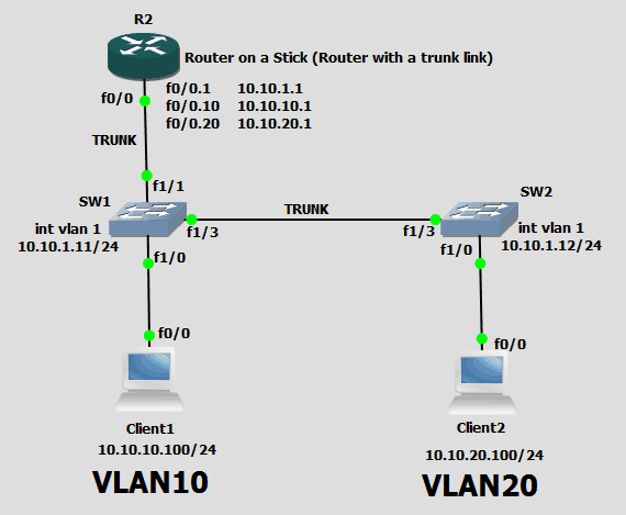
I have changed some aspects of the topology so that the configuration is not identical (what fun would that be?) but the goal is to allow traffic generated from a host in one VLAN to reach, and return from, another VLAN. A GNS3 user can generate a screenshot of the topology of a project at any time using the camera icon:
There is also the option of clicking File and then Take a screenshot, but the camera icon is so much more fun. Anyway, here is a screenshot of my topology for this blog:
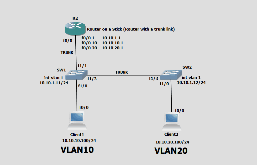
Topology view
The client machines are really routers assuming the roles of IP endpoints. To accomplish this, I have disabled IP routing on each of them using this command: (config)# no ip routing
When IP routing is disabled, another command which is normally ignored by routers now takes on a significant role. This command is: (config)# ip default-gateway x.x.x.x
Normally routers have a gateway of last resort which results from a default route. When IP routing is disabled, the ability to get to remote networks results from the above ip default-gateway command.
The next order of business is to explain why there is a picture of a computer if the device is actually a router. This is another cool feature of GNS3. Take a look:
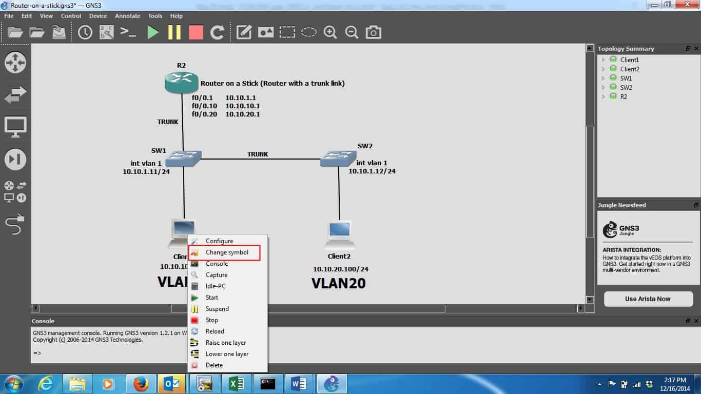
By right-clicking directly on the device, I see the drop-down menu shown. One of the choices is Change symbol. If you choose this option, you can choose from a large number of devices – one of which is the computer I have shown in my topology.
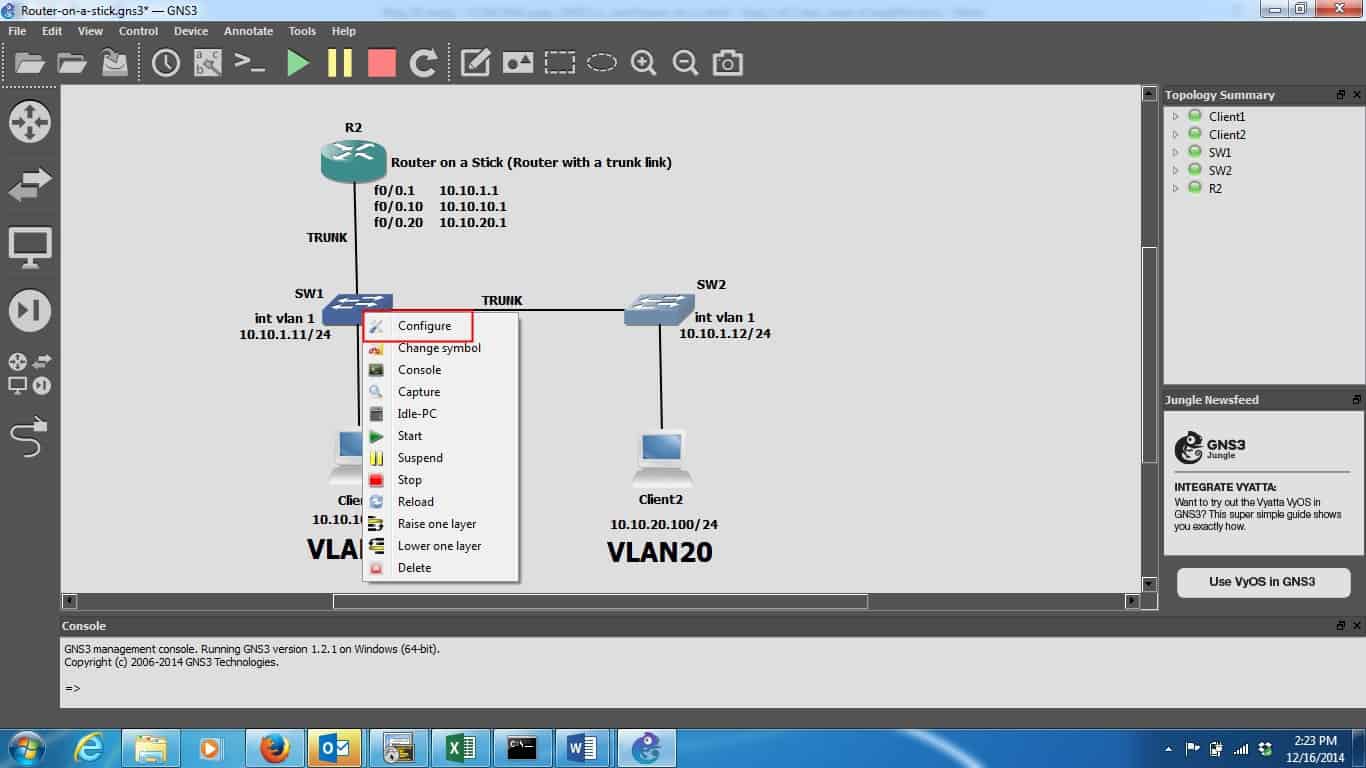
The same goes for the switches – SW1 and SW2. They are both routers which are assuming the role of Layer 2 switches in my scenario. They are both 3725 routers which have been configured with an etherswitch module. This configuration allows virtually all of the commands you need in order to practice for your CCNA Routing and Switching exam. Here is how to configure the etherswitch module. Right click on the router (while it is shut down), and one of the options is Configure:
Once that is selected, it looks like this:
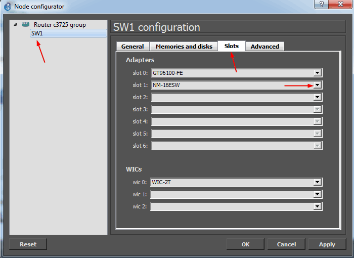
The NM-16ESW is the etherswitch module which I have selected to occupy slot 1 in my device. Down below you see that, if the device supports it, you can add serial interfaces to your device. I did so just to show it can be done, but that WIC-2T in the picture is not used in my topology.
R2 is also a 3725-series router which I have left performing the role of a router, in this case, it has been configured as a Router-on-a-stick. The client configuration is straightforward – I put an ip address on each of the f0/0 interfaces, set speed and duplex, and no shut them. I added VLANs on each of the two switches – one for each client. The method of adding VLANs on an etherswitch module is a little different from how it is done on a 2900 series switch, but the end result is the same. Here is how to create VLANs on an etherswitch module in GNS3:
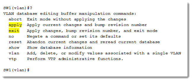
From privileged exec mode, type vlan database. Then create the desired VLANs with the command vlan xx (where xx is the desired VLAN ID). On SW1, it look like this:
SW1#vlan database
SW1(vlan)#vlan 10 (for example)
Once you are finished creating VLANs, apply your settings and then exit the vlan database mode. Here is the question mark help information from that mode:
The command to view the VLANs you have created is show vlan-switch. Here is the output of that command on SW1:
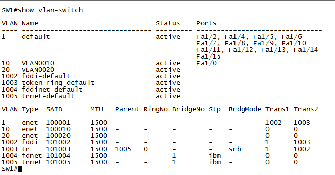
As you can see, I have created both VLAN 10 and 20 on this switch. I have done the same thing on SW2. I have also configured each client to be assigned to its respective VLAN. You can see in the output above that VLAN 10 is active on port Fa1/0. The corresponding configuration exists for Client2 on SW2. I have configured a trunk link between my two switches. A note on the interface labels. You will not that the interfaces that are in use do appear in the topology diagram. This is configurable by the user. If you want them to be visible, click on this icon:

If you want them to go away, click it again. One other note on view preference. Normally, GNS3 will show green dots on your links that are up. If you don’t like this, you can disable that feature in Edit > Preferences > and then you get this window:
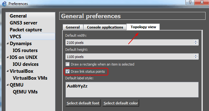
Select Topology view and then choose to either show the link status points or not to show them. In the Topology view picture above, the link status lights are not visible. Here is what it looks like when the link status indicators are enabled:
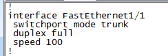
I configured the link from SW1 to R2 as a trunk link using the following configuration on SW1:
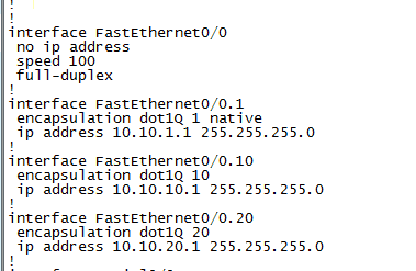
The last step is the actual Router-on-a-stick configuration on R2. That configuration is shown below:
Now that all the configuration is done, let’s see if GNS3 will show connectivity FROM Client 1 all the way TO Client2 and BACK. Let’s generate a ping from Client1 and note the output:
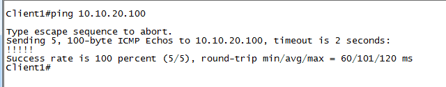
Since 10.10.20.100 is the ip address of Client2, it seems that our Router-on-a-stick is working. Let’s examine the routing table of R2:
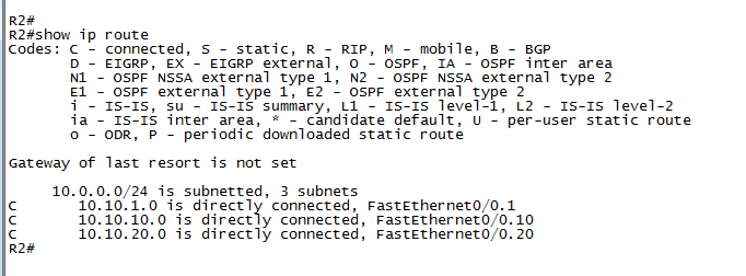
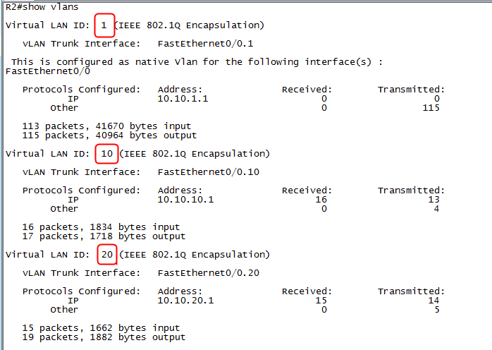
Our subinterface subnets all appear as they should. We can even verify that R2 is 802.1q VLAN aware with the show vlans command:
So if you are already familiar with GNS3, you will find that it functions much the same as before. There is much different under the hood – check out their FAQ and documentation if you want to know what happened behind the scenes. Nevertheless, I heartily recommend it as a tool to practice the lab scenarios you will need in order to be fully prepped to take the exam to get your CCNA Routing and Switching.
If you have any questions or comments, please feel free to post them.
Enjoy!
Mark Jacob
Cisco and CompTIA Network + Instructor – Interface Technical Training
Phoenix, AZ


A Simple Introduction to Cisco CML2
Mark Jacob, Cisco Instructor, presents an introduction to Cisco Modeling Labs 2.0 or CML2.0, an upgrade to Cisco’s VIRL Personal Edition. Mark demonstrates Terminal Emulator access to console, as well as console access from within the CML2.0 product. Hello, I’m Mark Jacob, a Cisco Instructor and Network Instructor at Interface Technical Training. I’ve been using … Continue reading A Simple Introduction to Cisco CML2
Creating Dynamic DNS in Network Environments
This content is from our CompTIA Network + Video Certification Training Course. Start training today! In this video, CompTIA Network + instructor Rick Trader teaches how to create Dynamic DNS zones in Network Environments. Video Transcription: Now that we’ve installed DNS, we’ve created our DNS zones, the next step is now, how do we produce those … Continue reading Creating Dynamic DNS in Network Environments
Cable Testers and How to Use them in Network Environments
This content is from our CompTIA Network + Video Certification Training Course. Start training today! In this video, CompTIA Network + instructor Rick Trader demonstrates how to use cable testers in network environments. Let’s look at some tools that we can use to test our different cables in our environment. Cable Testers Properly Wired Connectivity … Continue reading Cable Testers and How to Use them in Network Environments
See what people are saying...