Spanning Tree Protocol (STP) takes root
Spanning Tree Protocol (STP) takes root
So you want redundancy in your network. You want multiple links to the same destination. You want fall back plan on top of fall back plan. But multiple redundant links lead to a dangerous situation – the possibility of a loop in your sacred layer two fabric. How is this situation resolved? Enter Spanning Tree Protocol (STP).
First invented in 1985 by Radia Perlman working for Digital Equipment Corporation, then standardized by the IEEE in 1990 as 802.1d, STP seeks to prevent loops in an Ethernet LAN. If you are seeking certification at the CCNA level, or if you are a network admin who wants a deeper understanding of the network, then delve into the inner workings of this not-so-brand-new protocol.
First off, it is good to note that there have been modifications to the original 802.1d standard as time has progressed, and the end result is still a loop-free layer two topology, but the convergence time has dropped significantly. We are devoting our attention here to the original standard, workings, and terminology of the early 802.1d standard to introduce ourselves to the topic.
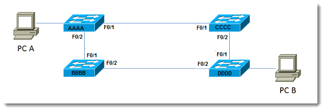
When a multiple-switch network exists and multiple links connect the switches, a loop is possible, as shown below:
PC A has more than one way to get to PC B, which is a good thing. Unfortunately, the fact that there are two possible paths means that there exists the potential for a loop. What STP does is to analyze the paths, determine which link or links will be live, and block the unneeded ones.
Let’s say the switch network shown above goes live – that is, those four switches are plugged in at the same time – what happens in STP? The steps look like this:
1. Election of the root bridge
2. Determine path to root using cost
3. Determine port states
4. Stay loop free!
Let’s examine each of these steps. In step one, a root bridge (the big cheese head-honcho bridge) must be elected. As with any election, ballots must be cast. The ballots are cast in the form of BPDUs, which are bridge protocol data units. These are sent every two seconds by default. The winner of the root bridge election is the one with the lowest Bridge ID (BID). The BID is comprised of two parts – the priority and the MAC address – concatenated to form the result which is used to determine the winner of the election. The default priority of Cisco switches is 32768. The MAC address is the layer two information associated with each particular switch. Since older switches will likely have MAC address with lower values than newer switches, a root bridge election left to its own devices (get it?…its own devices! That’s good stuff.) will generally obtain a result where the older switch wins out over the shiny expensive new switch you just installed. Not the result you want? Then influence the election. No, it’s not illegal, you can influence the results of the election without fear of prosecution. Since you can’t change the MAC address, the other alternative is to influence the priority. As mentioned, the default value is 32768, but who says you have to leave it at the default? So set the value lower (in increments of 4096) to influence the winner of the root bridge election. Your goal is to have the higher capacity switch located centrally within your network become the root bridge.
Step two of the process is to determine the best path to the root based upon the cost to get there. Cost is based upon the speed, or data rate, of links in the network. In the topology in our example, let’s say the top left switch is the root bridge. I have shown the topology again with some extra information, such as port identifiers and sample MAC addresses (just a piece of the MAC addresses for example purposes):
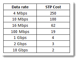
Assuming the priority values have not been changed from the default value of 32768, and that all links are 100Mbps, Switch AAAA wins the election based on the lowest MAC address value. Now the other switches must decide on the best route to the root for each of them. For Switch CCCC and Switch BBBB, the choice is obvious – they are both directly connected to the root. This means that each of them select FastEthernet 0/1 as the best path to the root. Let’s do a quick aside and add the topic of cost into the mix. Since our assumption is that all links are 100 Mbps, how is the STP cost obtained?
The 802.1d published cost values are presented in the following table:
So the cost for BBBB to get to the root is 19. The cost for CCCC to get to the root is 19. The slightly more involved part of this is what happens for Switch DDDD. Switch DDDD has two paths to the root. The cost through CCCC is 19 + 19, or 38. The cost through BBBB is 19+19, or 38 also. So in the case of identical results, what breaks the tie? If there exists more than one least-cost paths to the root, the tie-breaker is to select the neighbor with the lowest bridge ID. For Switch DDDD, which neighbor is that? Since BBBB is lower than CCCC, Switch DDDD selects the path through Switch BBBB (meaning the exit interface is F0/2) as the least-cost path.
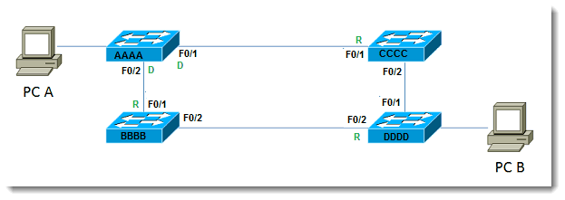
The third piece is to determine final port states. Possible states discussed here are Designated Ports, Root Ports, and Blocking Ports. Let us consider root ports. Using the information discussed above, we observe that for Switches BBBB and CCCC, port F0/1 for each becomes a root port. All that means is that if you follow the root port, it will eventually lead to the root. In this case, eventually is pretty fast, since the switches are directly connected. At other times, there may be more than one switch between one switch in your organization and the root. Nevertheless, following the root port will lead to the root bridge. Let’s take a moment to exercise our mental prowess: If root ports lead TO the root, will the root bridge ever have a root port? A flurry of mental activity leads to the inevitable conclusion that no, root bridges do not have root ports – they ARE the root, they don’t need to GET TO the root. The term for this is Designated Port. All active ports on the root bridge are in the Designated state. Don’t allow the terminology to confuse you. A designated port is just a port that is forwarding.
The remaining state we wish to cover is blocking. Now that we have determined the Designated and Root Ports in our topology, which port is blocked to prevent a loop? Let us redraw the diagram with the known states depicted:
What happens to port F0/2 on BBBB? Switch DDDD has selected its own port F0/2 as the root, as explained above. If Switch BBBB were now to block its port F0/2, it would destroy the ability of Switch DDDD to get to the root. Since Switch BBBB already has chosen its root port, port F0/2 cannot become a root port. Keep in mind that each LAN segment requires one Designated Port whose job it is to transmit traffic from that segment to the root. With that requirement in place, we deduce that for Switch BBBB, port F0/2 becomes a Designated port. The last determination that must be made is what happens between Switches DDDD and CCCC. Since DDDD has already determined that its lowest cost neighbor is BBBB, the candidate for the Blocking Port must be between DDDD and CCCC. Since only one of them block, we must determine which one becomes the ‘blocker.’ The one who blocks is the one with the worst (highest) BID. Between CCCC and DDDD, DDDD loses this battle, and therefore blocks its port F0/1. Since DDDD is blocking, CCCC still counts port F0/2 as a Designated Port. Thus redundancy exists, but a loop is prevented. Let’s modify our diagram one more time with all the pieces in place:
This has been just a quick and simple view of spanning tree. Next time I would like to get a little deeper into the whole process, especially the default timers and what that means for your network, Spanning Tree Protocol (STP) has been around the block.
Until then, let this topic take root!!
Mark Jacob
Cisco Instructor – Interface Technical Training
Phoenix, AZ
You May Also Like
802.1d, multiple-switch network, Spanning Tree Protocol, STP
A Simple Introduction to Cisco CML2
0 3898 0Mark Jacob, Cisco Instructor, presents an introduction to Cisco Modeling Labs 2.0 or CML2.0, an upgrade to Cisco’s VIRL Personal Edition. Mark demonstrates Terminal Emulator access to console, as well as console access from within the CML2.0 product. Hello, I’m Mark Jacob, a Cisco Instructor and Network Instructor at Interface Technical Training. I’ve been using … Continue reading A Simple Introduction to Cisco CML2
Creating Dynamic DNS in Network Environments
0 643 1This content is from our CompTIA Network + Video Certification Training Course. Start training today! In this video, CompTIA Network + instructor Rick Trader teaches how to create Dynamic DNS zones in Network Environments. Video Transcription: Now that we’ve installed DNS, we’ve created our DNS zones, the next step is now, how do we produce those … Continue reading Creating Dynamic DNS in Network Environments
Cable Testers and How to Use them in Network Environments
0 727 1This content is from our CompTIA Network + Video Certification Training Course. Start training today! In this video, CompTIA Network + instructor Rick Trader demonstrates how to use cable testers in network environments. Let’s look at some tools that we can use to test our different cables in our environment. Cable Testers Properly Wired Connectivity … Continue reading Cable Testers and How to Use them in Network Environments




Pingback: Cisco Spanning Tree Protocol (STP) has been around the block | Interface Technical Training