Spanning Tree – the Roots Go Deeper!

While I have posted a couple of blogs regarding spanning-tree, the Layer 2 loop prevention mechanism that runs on Cisco switches, I wanted to post one with a few more switches and a bit more detail on the step-by-step process. Follow the steps as we proceed from a blank scenario to one in which all the switches, MAC addresses, ports, speeds, and costs are included. Seeing the process as it flows from beginning to end really helps solidify the concept. I hope it helps you!
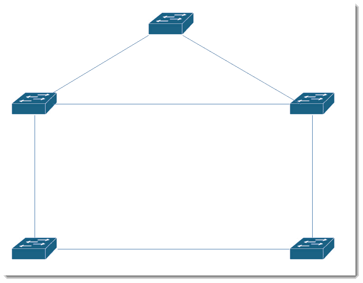
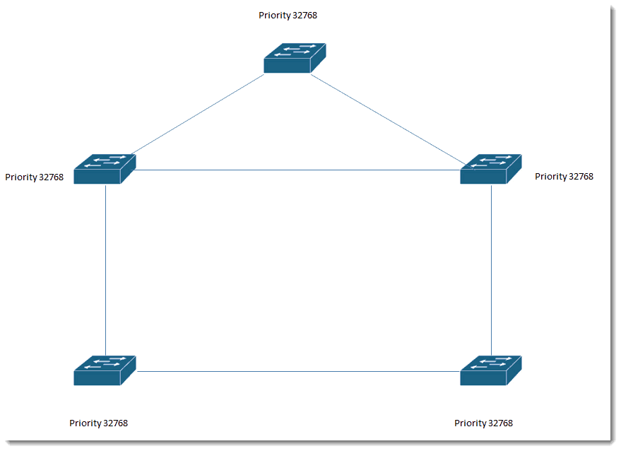
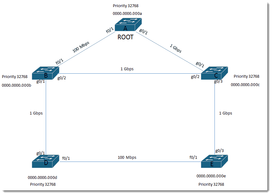
All switches have the default priority: 32768
Let’s put in some fake MAC addresses.
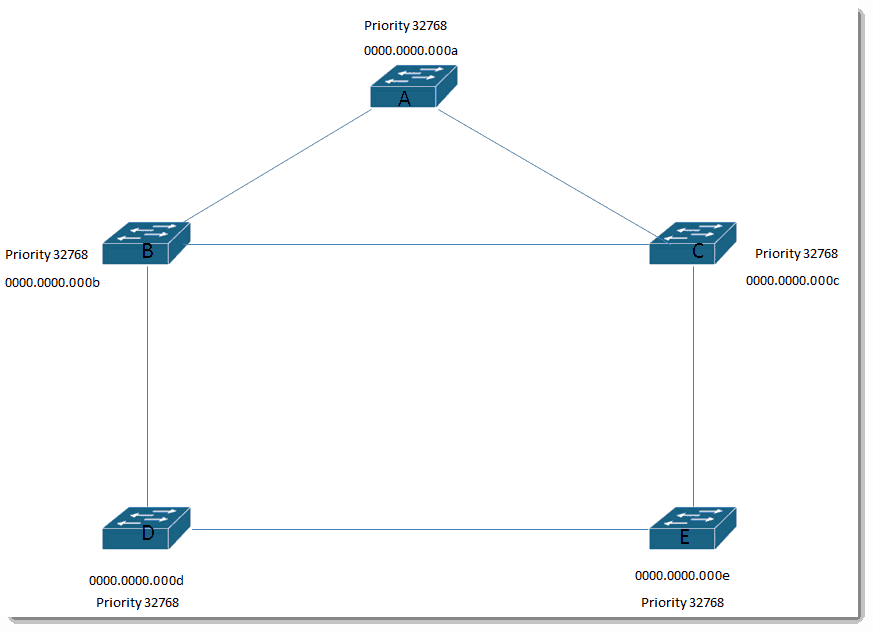
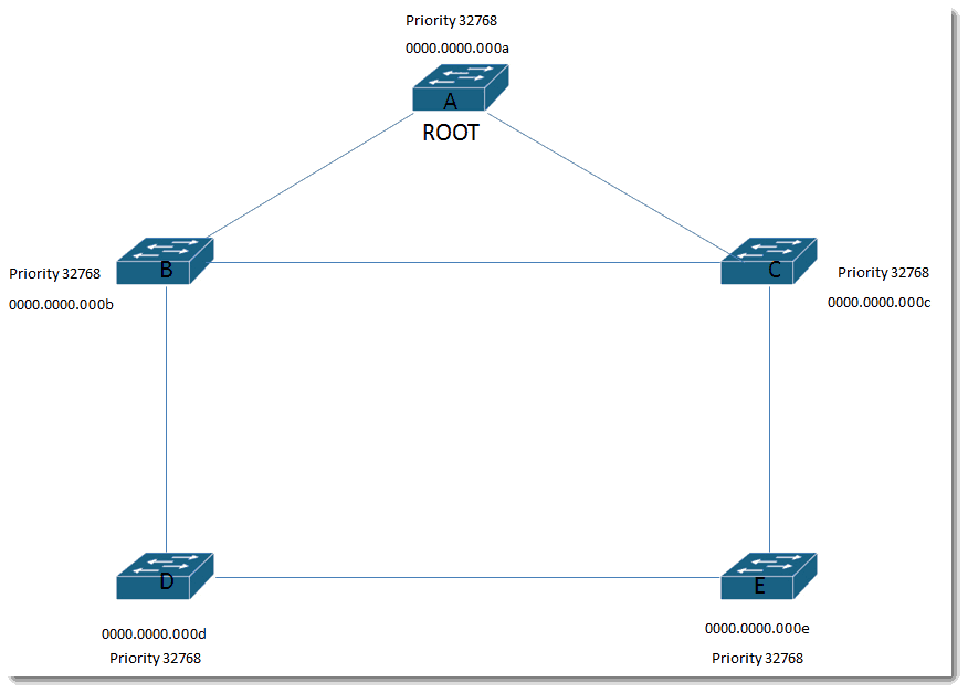
Based on the rule that Bridge ID = Priority and MAC address concatenated and lowest Bridge ID wins, Switch A becomes the root.
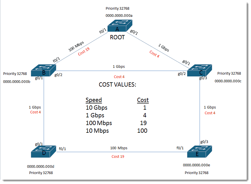
Let’s put some speeds and port identifiers on these links…
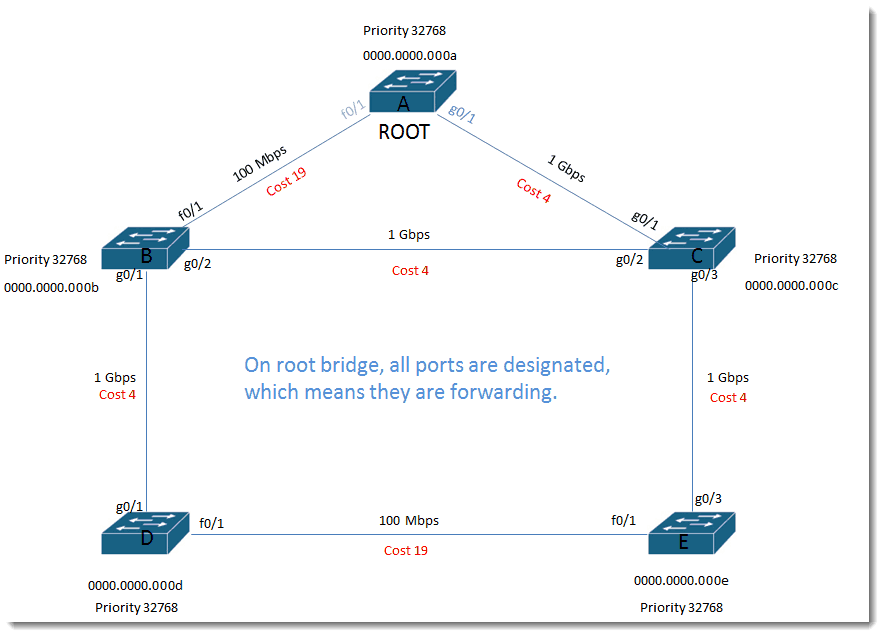
On root bridge, all ports are designated, which means they are forwarding.
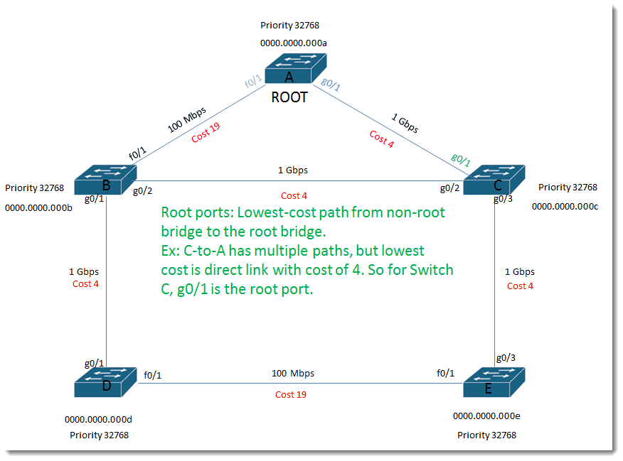
Root ports:
Lowest-cost path from non-root bridge to the root bridge. Ex: C-to-A has multiple paths, but lowest cost is direct link with cost of 4. So for Switch C, g0/1 is the root port.
Root ports:
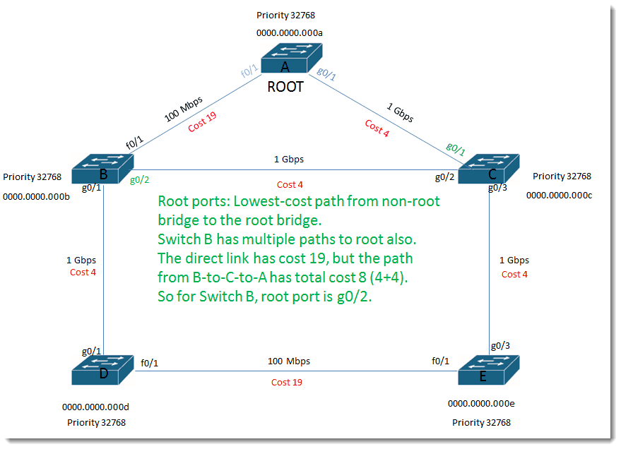
Lowest-cost path from non-root bridge to the root bridge. Switch B has multiple paths to root also. The direct link has cost 19, but the path from B-to-C-to-A has total cost 8 (4+4). So for Switch B, root port is g0/2.
Root ports:
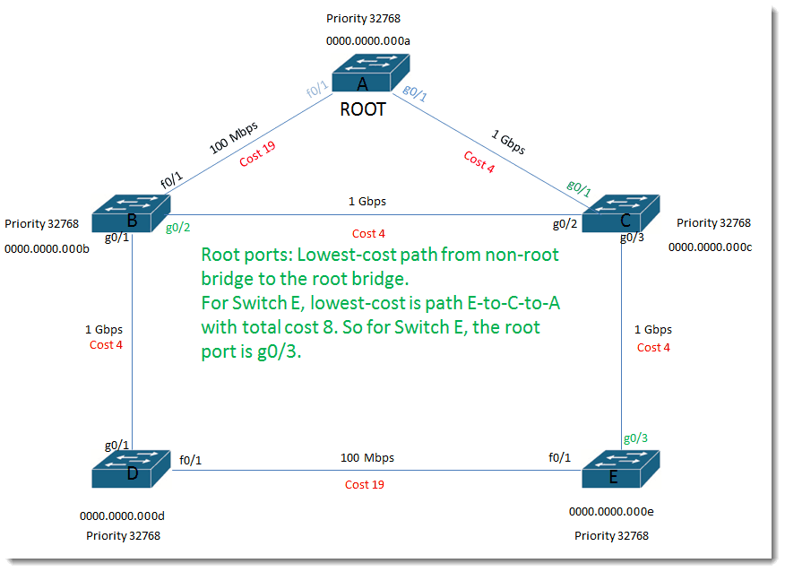
Lowest-cost path from non-root bridge to the root bridge. For Switch E, lowest-cost is path E-to-C-to-A with total cost 8. So for Switch E, the root port is g0/3.
Root ports:
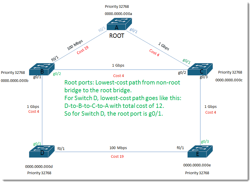
Lowest-cost path from non-root bridge to the root bridge. For Switch D, lowest-cost path goes like this: D-to-B-to-C-to-A with total cost of 12. So for Switch D, the root port is g0/1.
Designated ports:
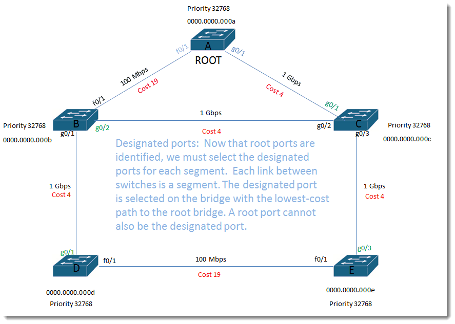
Now that root ports are identified, we must select the designated ports for each segment. Each link between switches is a segment. The designated port is selected on the bridge with the lowest-cost path to the root bridge. A root port cannot also be the designated port.
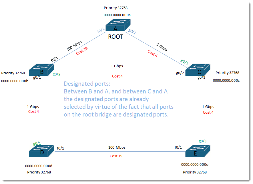
Designated ports:
Between B and A, and between C and A the designated ports are already selected by virtue of the fact that all ports on the root bridge are designated ports.
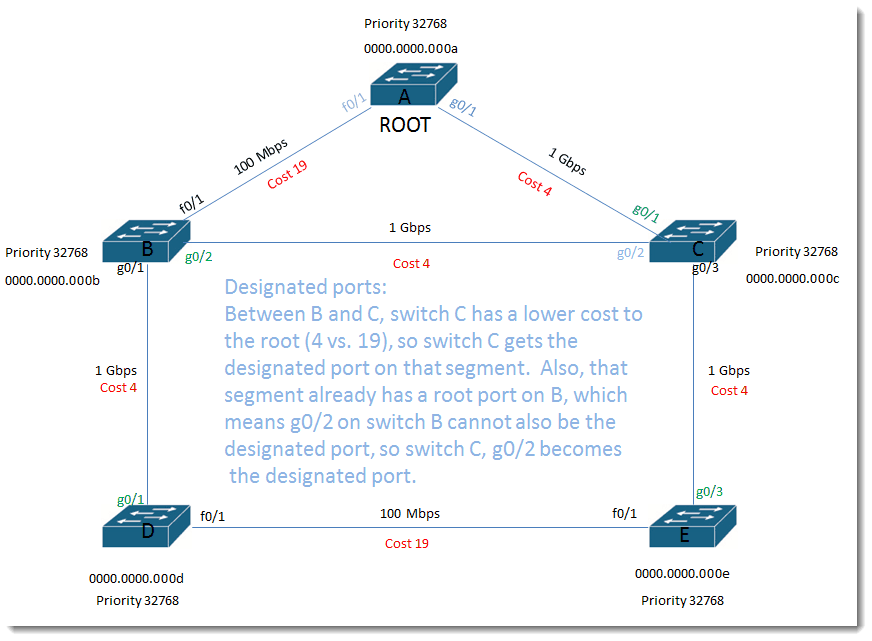
Designated ports:
Between B and C, switch C has a lower cost to the root (4 vs. 19), so switch C gets the designated port on that segment. Also, that segment already has a root port on B, which means g0/2 on switch B cannot also be the designated port, so switch C, g0/2 becomes the designated port.
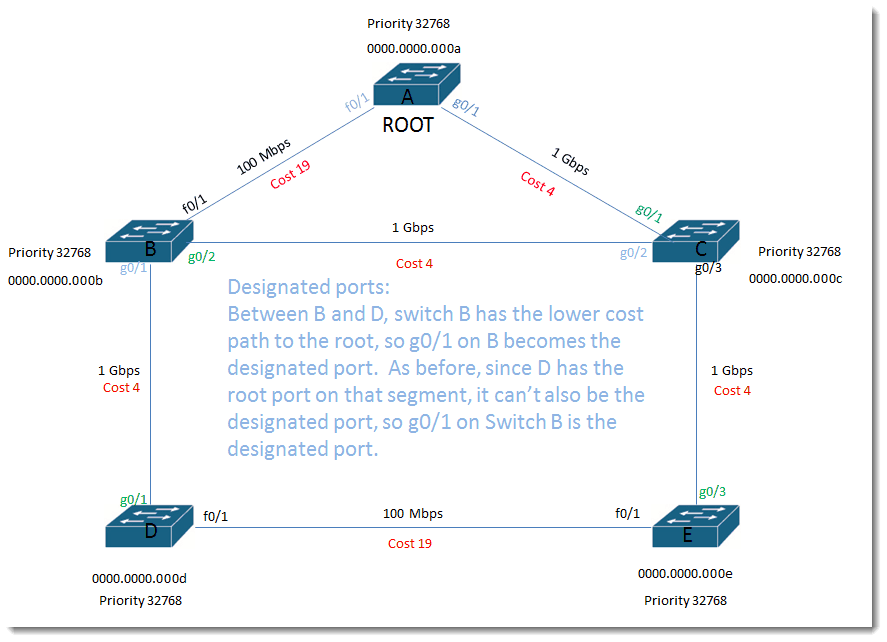
Designated ports:
Between B and D, switch B has the lower cost path to the root, so g0/1 on B becomes the designated port. As before, since D has the root port on that segment, it can’t also be the designated port, so g0/1 on Switch B is the designated port.
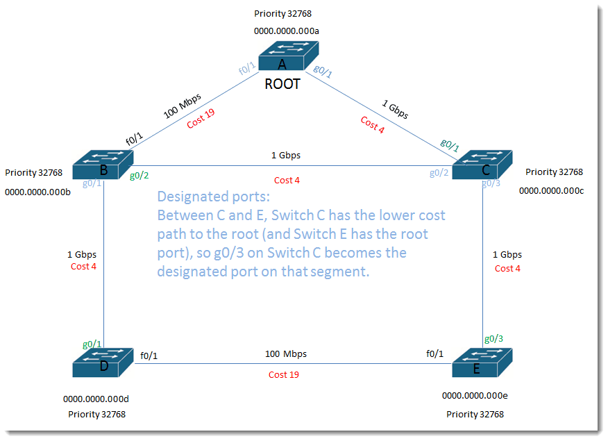
Designated ports:
Between C and E, Switch C has the lower cost path to the root (and Switch E has the root port), so g0/3 on Switch C becomes the designated port on that segment.
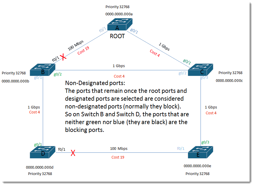
Non-Designated ports:
The ports that remain once the root ports and designated ports are selected are considered non-designated ports (normally they block). So on Switch B and Switch D, the ports that are neither green nor blue (they are black) are the blocking ports.
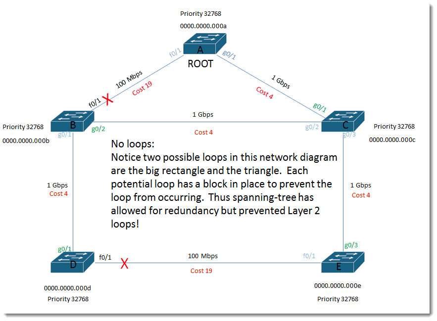
No loops:
Notice two possible loops in this network diagram are the big rectangle and the triangle. Each potential loop has a block in place to prevent the loop from occurring. Thus spanning-tree has allowed for redundancy but prevented Layer 2 loops!
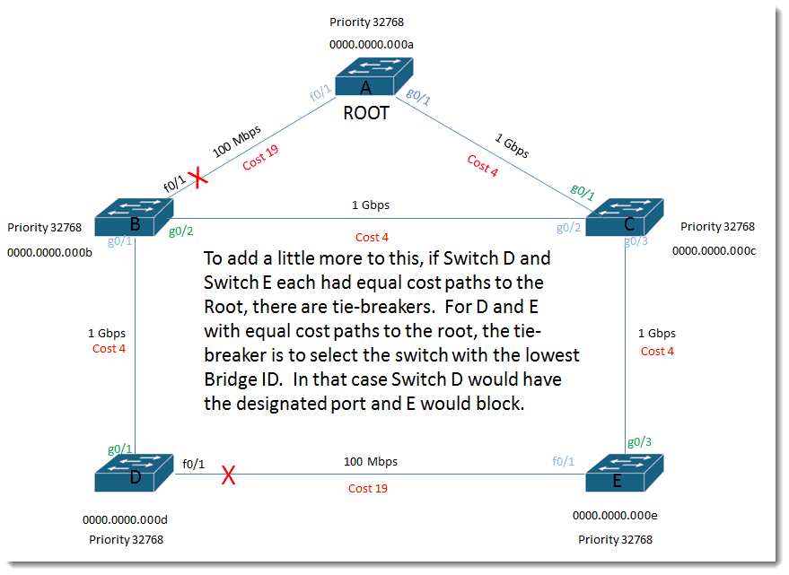
To add a little more to this, if Switch D and Switch E each had equal cost paths to the Root, there are tie-breakers. For D and E with equal cost paths to the root, the tie-breaker is to select the switch with the lowest Bridge ID. In that case Switch D would have the designated port and E would block.
All other factors being the same: If Switch D and E had two links between them (not ether-channeled) and also had equal cost paths to the root, the tie would be broken based on lowest Bridge ID and then on port priority.
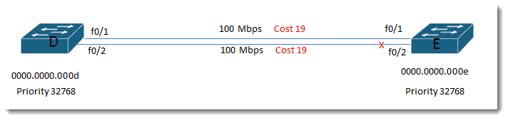
Default port priority starts at 128, so port 1 would have priority 128.1 and port 2 would have priority 128.2. Lowest priority wins so Switch E would choose to block its port which did not have the lower priority, which would mean E would block port f0/2.
Even though it seems that Layer 2 access layer solutions are slowly being replaced by blazing fast Layer 3 solutions, it pays as a network admin to understand how spanning tree makes its decisions.
I hope you found value in this blog.
Until next time…
Mark Jacob
Cisco Instructor – Interface Technical Training
Phoenix, AZ


")

A Simple Introduction to Cisco CML2
Mark Jacob, Cisco Instructor, presents an introduction to Cisco Modeling Labs 2.0 or CML2.0, an upgrade to Cisco’s VIRL Personal Edition. Mark demonstrates Terminal Emulator access to console, as well as console access from within the CML2.0 product. Hello, I’m Mark Jacob, a Cisco Instructor and Network Instructor at Interface Technical Training. I’ve been using … Continue reading A Simple Introduction to Cisco CML2
Creating Dynamic DNS in Network Environments
This content is from our CompTIA Network + Video Certification Training Course. Start training today! In this video, CompTIA Network + instructor Rick Trader teaches how to create Dynamic DNS zones in Network Environments. Video Transcription: Now that we’ve installed DNS, we’ve created our DNS zones, the next step is now, how do we produce those … Continue reading Creating Dynamic DNS in Network Environments
Cable Testers and How to Use them in Network Environments
This content is from our CompTIA Network + Video Certification Training Course. Start training today! In this video, CompTIA Network + instructor Rick Trader demonstrates how to use cable testers in network environments. Let’s look at some tools that we can use to test our different cables in our environment. Cable Testers Properly Wired Connectivity … Continue reading Cable Testers and How to Use them in Network Environments
See what people are saying...