Understanding EIGRP named mode wide-metric computation

In a previous blog I discussed running EIGRP named mode in GNS3. In that blog, I promised to dig a little deeper into how the results of the computations were reached. I have published a couple of blogs which strive to display the classic formula in human friendly form. I will attempt the same thing in this blog. It is important to note that the wide metric formula I will be showing in this blog is for 1 Gigabit links and slower. The formula is adjusted for 10 Gig and above. I will leave that for a future blog.
For instructor-led Cisco CCNA Certification Training, see our class schedule.
First off, let’s take a look at the topology I built inside GNS3 (v1.3.9)
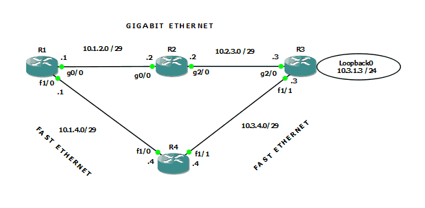
Figure 1-Lab topology
As figure 1 shows, R1, R2, and R3 are all connected using GigabitEthernet. The connection from R1 to R4 to R3 is FastEthernet.
I have configured EIGRP named mode on all four routers, and neighbor relationships have formed where expected. The focus of attention here is the loopback interface hanging off R3. Clearly the least cost path from R1 to that destination is through R2. Let’s take a look at the routing table of R1 in our converged network:
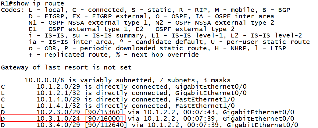
Figure 2-Routing table of R1
Notice that R1 knows about the 10.3.1.0 destination network and that the metric showing in the routing table is 16000. How does the router compute this number? Using the EIGRP metric calculation formula, of course! There are numerous web references to this formula, but an excellent Cisco reference can be found here. All the subtle nuances and reasonings as to why an updated formula is necessary and why 64 bit metrics are now a necessity can be found by reading from that webpage. I include a table from that source as figure 3:
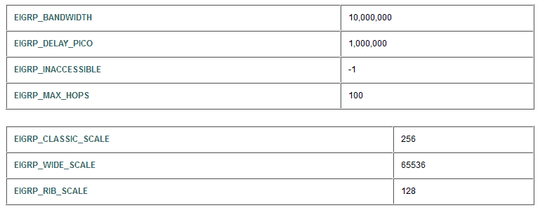
Figure 3-Constants used in EIGRP wide metric calculation
Using the above table as a reference, let’s see if we can duplicate the router’s computation. I will abbreviate the names in the table in figure 3 to shrink to formula. Here is a guide to understanding my result:
- ps = picoseconds (delay is counted in picoseconds [1 trillionth of a second]). Value obtained from actual network information.
- EWS = EIGRP WIDE SCALE = 65,536
- EDP = EIGRP DELAY PICO= 1,000,000
- EBW = EIGRP BANDWIDTH = 10,000,000
- mbw = Minimum bandwidth in path to destination. Value obtained from actual network information.
The full formula, as in classic EIGRP, is more involved, but if the ‘K’ values are left at their default values, the formula (for 1Gig and slower) simplifies to the following:
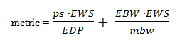
The first portion of the formula addresses the Delay aspect of EIGRP’s metric, and the second half addresses the Bandwidth portion.
We now type the command which reveals the necessary numbers, shown in figure 4:
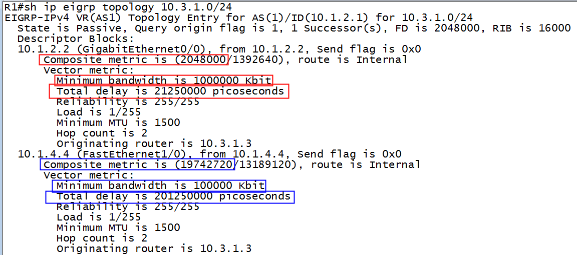
Figure 4-Topology table of R1
The metric using the GigabitEthernet path (the numbers in red boxes) is found thusly:
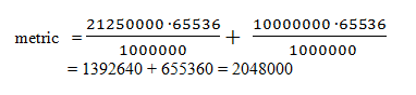
Using the rib-scale of 128, we take the result from above and divide, obtaining:
2048000 ÷128=16000
Sure enough, refer back to figure 2 and you will see the number 16000 as the best path metric to the destination network, and therefore is installed in the routing table.
If we want to check our consistency, let’s see what happens if we force R1 to use the FastEthernet path. Let’s kill the g2/0 interface on R2 and observe the result in R1’s routing table. We will use the blue numbers from figure 4 to make our prediction. If our math calculations are consistent, we should see the following result in R1’s newly converged routing table:
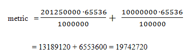
Applying the rib-scale (divide by 128) factor to our result:
19742720 ÷128=154240
There is the prediction – 154240. Let’s see if that number appears in the routing table of R1:
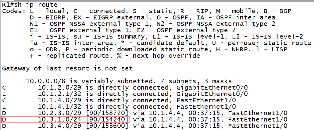
Figure 5-Routing table of R1
How about that?! Sure enough, 154240 is the new metric once we disabled the path through R2.
My goal here is to present the formula and the computations in a way that is easily followed by the human eye. I hope I have succeeded. As noted at the outset, this computation changes again in networks with links faster than 10 Gig, so if you are manually performing these computations and your results differ, verify that your link speeds fall within the constraints of this blog. Happy path manipulation!!
If you have any comments or questions, please feel free to post them….
Until next time.
Mark Jacob
Cisco and CompTIA Network + Instructor – Interface Technical Training
Phoenix, AZ


")
A Simple Introduction to Cisco CML2
Mark Jacob, Cisco Instructor, presents an introduction to Cisco Modeling Labs 2.0 or CML2.0, an upgrade to Cisco’s VIRL Personal Edition. Mark demonstrates Terminal Emulator access to console, as well as console access from within the CML2.0 product. Hello, I’m Mark Jacob, a Cisco Instructor and Network Instructor at Interface Technical Training. I’ve been using … Continue reading A Simple Introduction to Cisco CML2
Creating Dynamic DNS in Network Environments
This content is from our CompTIA Network + Video Certification Training Course. Start training today! In this video, CompTIA Network + instructor Rick Trader teaches how to create Dynamic DNS zones in Network Environments. Video Transcription: Now that we’ve installed DNS, we’ve created our DNS zones, the next step is now, how do we produce those … Continue reading Creating Dynamic DNS in Network Environments
Cable Testers and How to Use them in Network Environments
This content is from our CompTIA Network + Video Certification Training Course. Start training today! In this video, CompTIA Network + instructor Rick Trader demonstrates how to use cable testers in network environments. Let’s look at some tools that we can use to test our different cables in our environment. Cable Testers Properly Wired Connectivity … Continue reading Cable Testers and How to Use them in Network Environments
See what people are saying...