Understanding Fiber Optic in Network Environments

This content is from our CompTIA Network + Video Certification Training Course. Start training today!
In this post, CompTIA Network + instructor Rick Trader covers fiber optic cables and their specific use in network environments.
A common type of cable you’re going to come across inside your corporate network is going to be fiber optics. Fiber is our most common cable if we want to have high speed data (Up to four gigabytes per second).
Fiber Optic Properties
- Fiber optic cable can support data rates up to 4 Gbps over distances ranging from 2 km to 25 km
- Common fiber optic cables are classified based on the diameter of their course
- Optic connector is either ceramic or plastic ferrule
Depending on whether you are multi‑mode or single‑mode cable will control your distance of every cable. We’ll discuss single‑mode and multi‑mode latter.
What actually carriers our signal is in the center of our cable, referred to as a ferrule.
This center conductor is either going to be made of high‑quality plastic, or ceramic to carry our light signal through it.
Depending on the type of cable, (single‑core or multi‑core) it will control the thickness of the actual ferrule itself. Later we will discuss shining and polishing the ferrule.
The difference between single‑mode and multi‑mode.
Multi-Mode Fiber (MMF):
- Typically has a 62.5 micron core
- Light travels down the core in many rays
- Works with LED light sources of different wavelengths
Single-Mode Fiber (SMF):
- Very small core of about 9 microns
- Light travels down the cable in one ray
- Optimal for very fast transmissions
Multi‑Mode Fiber (MMF) is only going to be run in short distances. Normally, inside your organization running from something such as a patch panel to another room inside your facility. It might be running with inside the patch panel. It might be coming from your demarcation point which is the spot that comes inside your corporate environment where your ISP is coming in.
The size of a Multi-Mode (MMF) ferrule is 62.5 microns, whereas on Single-Mode (SMF) is 9 microns. It’s much difference in size.
Multi‑Mode allows us to carry multiple signals at the same time. Multiple different data paths. They’re going to do it by using different wavelengths of the light
Whereas if we’re working with Single‑Mode Fiber (SMF) is going to be done for long distances. For example, Single-Mode may by going from one facility to another facility that might be located on the other side of town, or going from one city to another city.
It has a 9‑micron ferrule. Only one piece of data can travel on the cable at a time.
When we’re looking at our cables, our cables will always have a transmit and receive ferrule on the end .
Later, we’ll see which end is a transmit and a receive when we plug the cable into a Cubic.
Types of Fiber Optic Connectors:
ST (Straight Tip)
- Bayonet Style
- Multi-Mode
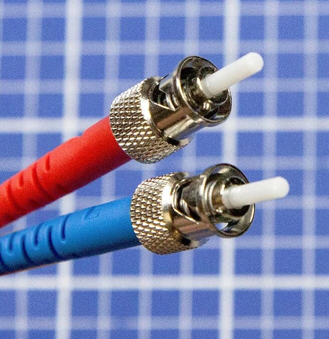
Our first connector is called an ST connector. Commonly referred to as a Straight Tip. ST connector, or Straight Tip connector, gets its name because of the actual ferrule itself.
These have dust covers on them. You always want to make sure you leave the dust covers on the ferrules, or over your conductor until you’re ready to put it in use.
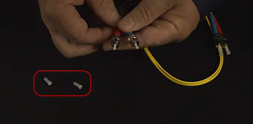
You’ll see, we have our ferrule. The fiber is so small we can’t see it. The white is a protective sheeting. Inside of the white is the ferrule itself.
This is a ST connector, or sometimes we refer to it as a Bayonet connector. If you remember the BNC connector, it looks a lot like a BNC connector. It snaps on, and it twists a quarter of a turn. This is typically going to be multi‑mode, which means it’s going to be inside of our organization. Commonly can be on our patch panels in our environment.
SC (Subscriber Connector)
- Push/Pull Design
- Single or Multi-Mode
- Gigabit Ethernet
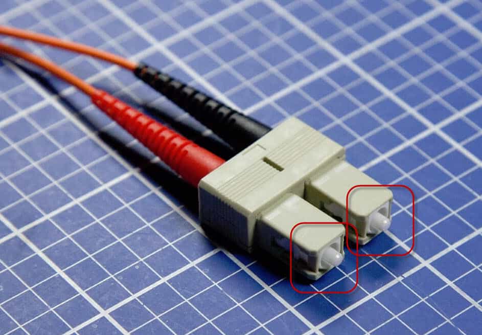
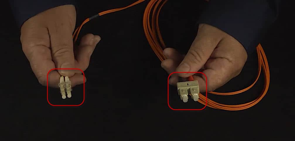
The next type of connector that we’re going to use is referred to as a Subscriber Connector, or an SC connector. The SC connector is much larger than the ST connector. The SC connector is going to be a push‑and‑pull design. We just push it in to plug it in, or we just pull it to unplug it out. It could both be single mode or multi‑mode.
If we’re going to do gigabit connections, which is going to be our faster connection over ST, we’d need to have at least an SC connector. Let’s take a look at what an SC connector looks like.
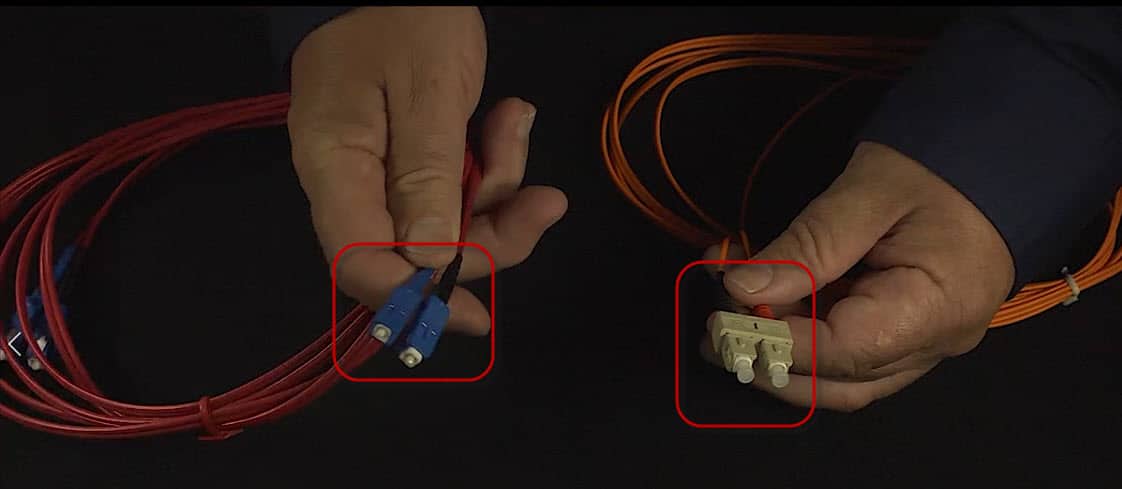
These are two different connectors. One, is a compound connector that’s all in one piece while the other is the same SC connector but it is separated.
Again, they have the dust covers on them. You can remove the dust covers when they’re not in use, and you have your actual semi‑conductors in them.
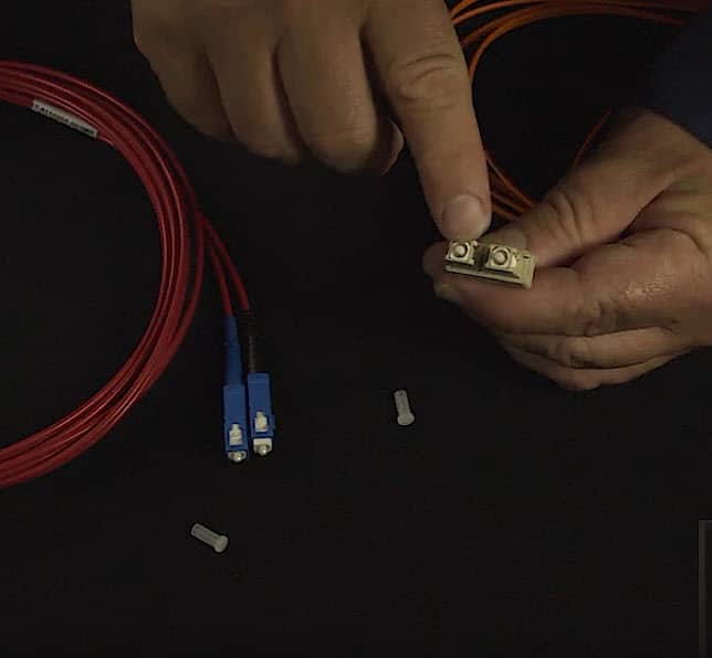
These are going to plug in to what’s referred to as a cubic, or a transceiver.
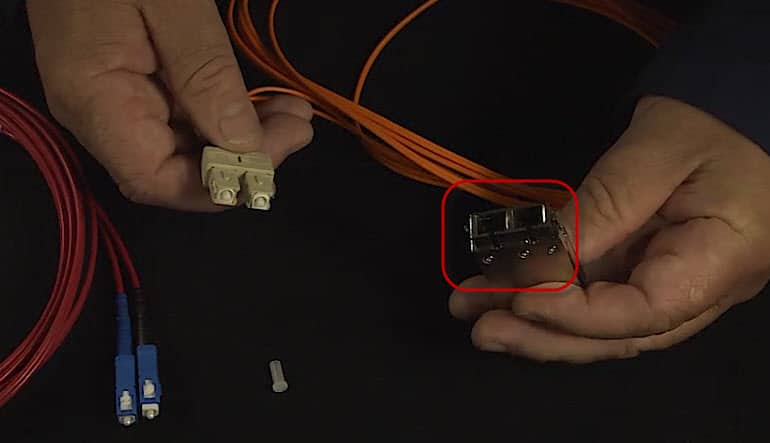
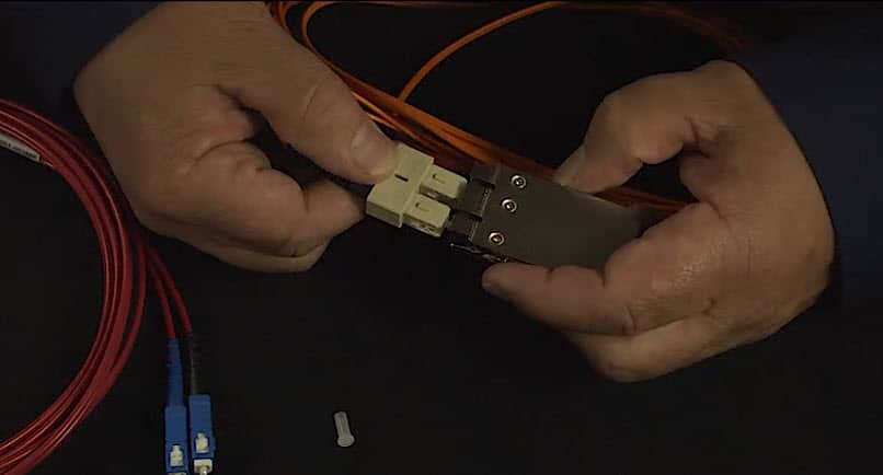
This transceiver can either be in the back of your computer, it could be in your switch, it could be in your router, it might be in your wireless device. If you notice, we have guides in this and this can only plug in one way. Notice, they can just pop in.
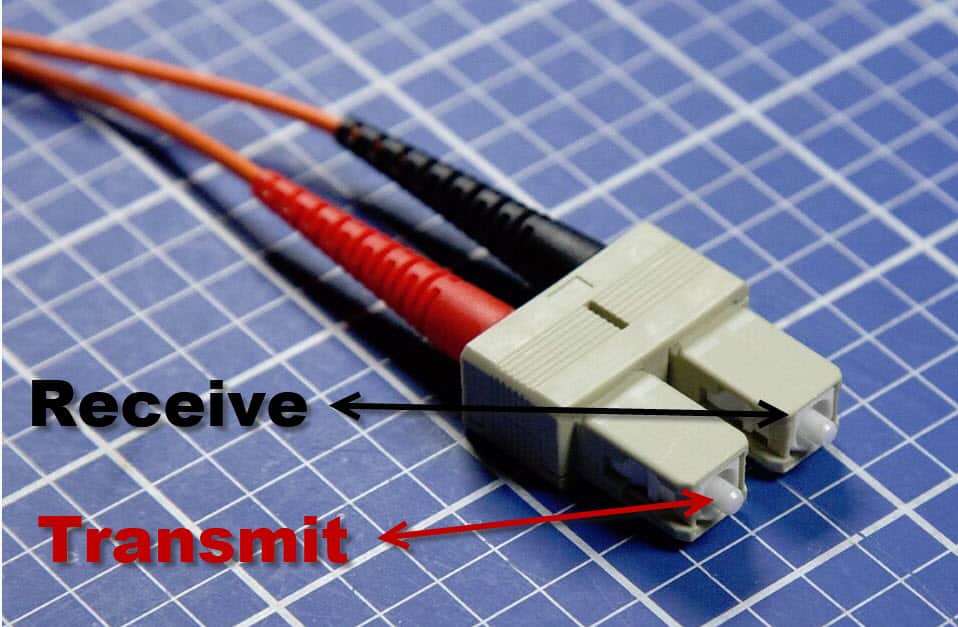
If we turn the transceiver over, notice there are directional arrows.
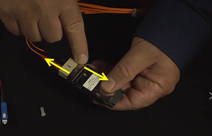
These are the receive and transmit directions of the fiber cable. If this is going on a patch panel, the receive and transmit are going to be straight through, or the same thing on both ends.
If you are going from a device, from one computer to another computer, make sure that you swap my connectors so that the transmit is connected to your receive input on one side. Then, your transmit from computer A is connected to the receive on the computer B.
Again, you just pull on it and it pulls out. You want to make sure that you put your dust connectors back on if you’re not using them.
This one does the same thing.
It’s also got guides on the back. They slide in just like any other one would. This one is a little bit easier to use.
If you are going from a computer to a computer, it will remember it and need to take the black from the transmitter on this side, to the receive on the other computer. Then, the receive on the other computer to the transmit in back. That’s how the SC connectors work.
LC (Lucent or Local Connector)
- Small From Factor
- Tabbed Push/Pull
- Gigabit and 10Gbe
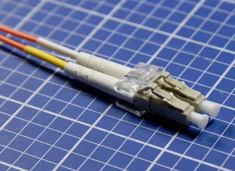
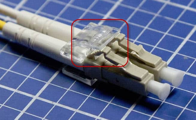
The next type of connector you might see is called a Lucid Connector, or a Local Connector. Lucid is a manufacturer and they’re the ones that first released the connectors. The LC connector, they refer to it as a small form connector. If you going to be doing gigabit or 10‑gigabit Ethernet, you will need to use an LC connector.
The difference between the LC and the SC is my LC is going to be tabbed. Notice, it’s got little tabs right here that’s going to lock it in to place. Again, it includes dust covers.
You’re going to hear three terms when you’re dealing with LC connectors.
Formats
- Physical Contact (PC)
- Ultra Physical Contact (UPC)
- Angled Physical Contact (APC)
These terms are dealing with the actual ferrule itself. A Physical Contact versus an Ultra Physical Contact is the amount polish that’s being applied to the ferrule itself. A UPC’s going to be highly polished, whereas the PC is just going to be a polished connector.
We also have a connector called the APC, or the Angled Physical Connector. What this one is going to do is, the ferrule itself, or the tip of the connector, is going to be angled just a little bit. Then, when you plug it in to a device, it’s a better connection. It creates less signal attenuation or signal loss between the two devices.
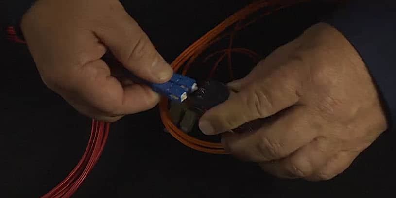
Let’s take a look at what a Lucid connector looks like with its transceiver.
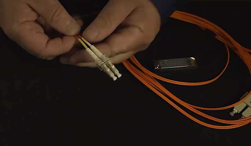
This is a Lucid connector.
They’re going to plug in to a mini cubic.
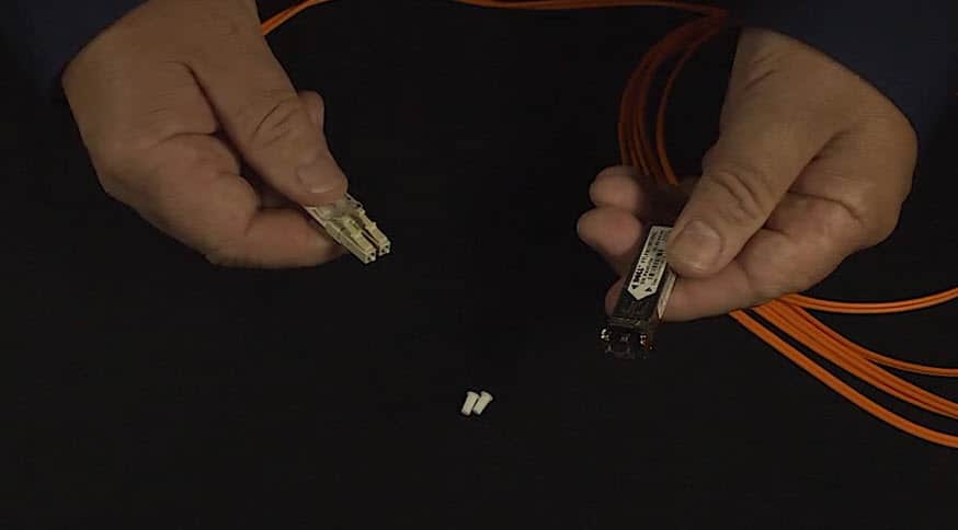
It also has the receive and transmit directional arrows on the back.
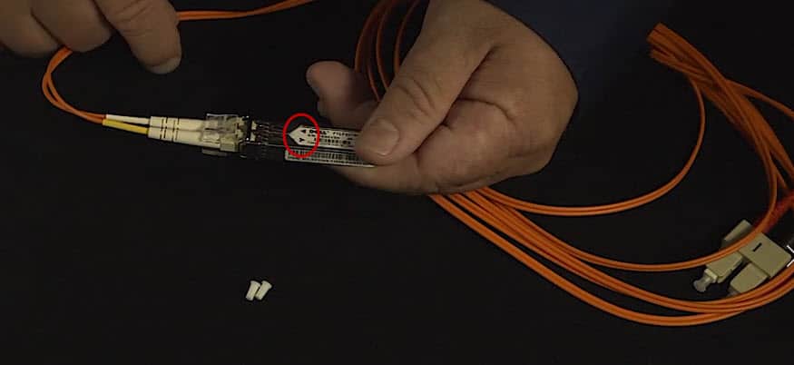
If you need to unplug it, you can just simply pull and unplug.
One thing to keep in mind with your cabling is you might have different connector on both ends.
You might have a SC on one end and an LC on the other end or you could have a SC on one end, and a LC or a ST on the other end. Depending on how you’re connecting from one side to the other side, you might have different connections.
MTRJ (Mechanical Transfer Registered Jack)
- Small Form Factor
- Duplex
- Multi-Mode
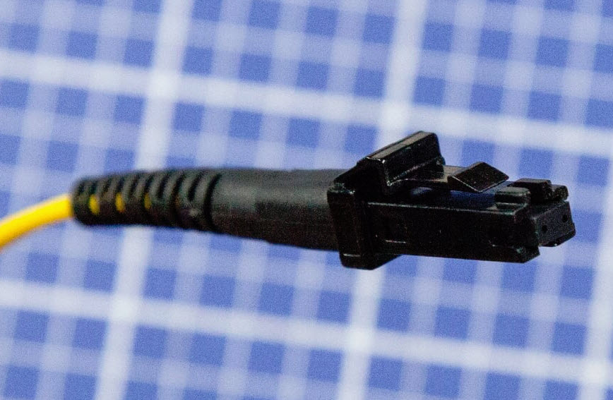
The last connector that you might see in fiber is called a Mechanical Transfer Registered Jack (MTRJ). It’s going to be a multi‑mode connector, which means it’s going to be for internal. It’s going to be, be able to duplex, meaning, it can send multiple signals down the cable at the same time.
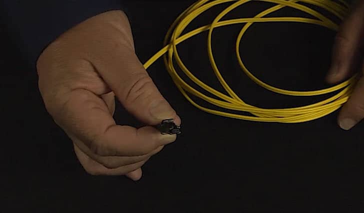
This cable. Notice it plugs in, it looks like an RJ45 connector. It’s bigger than an RJ11, but smaller than an RJ45.
This connector is used in most cases if you’re going from your patch panel, and you want to go to a computer, or you want to go from a patch panel to a wireless switch, or wireless hub, or you’re going from your patch panel to an actual router is when you’ll see the MTRJ connector.
Notice it looks a lot like a RJ45 connector. It is a little smaller than RJ45, but larger than an RJ11, which is your phone.
It is keyed just like other connectors so that it only goes in one way and it locks in to place, it’s got a little snap so that when it is plugged in, it makes a secure connection to your computer.
Patch Cords
Optical Multi-Mode (OM)
- OM1 (Beige)
- OM2 (Black)
- OM3 and OM4 (Aqua)
SMF (Blue)
APC (Green)
- Angled Physical Contact
When identifying patch panels and fiber, they will be color coded by the manufacturing industry.
We have what’s called Optical Multi‑Mode, or OM. There are four different versions all based on speed, and all based off of how the ferrule has been polished.
OM1, the cable and the connector will always be beige. OM2, the connector and the cable will be black. OM3 and OM4 are going to be aqua in color.
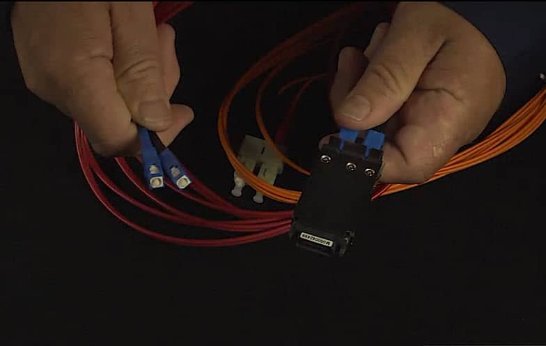
Single‑mode fiber will be blue.
If I have an APC connector, (the one with the angled ferrule) will be green.
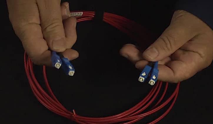
This blue connector informs us that this is going to be a single‑mode fiber. It’s not a multi‑mode.
If we look at another fiber cable, notice the connectors are beige.
These are going to be OM1 connectors.
Those are just standards if you’re doing multi‑mode versus single‑mode.
Also, your ST connectors will always be single‑mode. You don’t have to worry about color‑coding them.
For CompTIA Network + certification, you will need to be able to identify the different types of connectors, whether or not they’re multi‑mode or single‑mode, and then the most common patch panel colors for our cables.
Until next time….
Rick Trader
CompTIA Network + Instructor – Interface Technical Training
Phoenix, AZ
Video Certification Training: CompTIA Network +


")
A Simple Introduction to Cisco CML2
Mark Jacob, Cisco Instructor, presents an introduction to Cisco Modeling Labs 2.0 or CML2.0, an upgrade to Cisco’s VIRL Personal Edition. Mark demonstrates Terminal Emulator access to console, as well as console access from within the CML2.0 product. Hello, I’m Mark Jacob, a Cisco Instructor and Network Instructor at Interface Technical Training. I’ve been using … Continue reading A Simple Introduction to Cisco CML2
Creating Dynamic DNS in Network Environments
This content is from our CompTIA Network + Video Certification Training Course. Start training today! In this video, CompTIA Network + instructor Rick Trader teaches how to create Dynamic DNS zones in Network Environments. Video Transcription: Now that we’ve installed DNS, we’ve created our DNS zones, the next step is now, how do we produce those … Continue reading Creating Dynamic DNS in Network Environments
Cable Testers and How to Use them in Network Environments
This content is from our CompTIA Network + Video Certification Training Course. Start training today! In this video, CompTIA Network + instructor Rick Trader demonstrates how to use cable testers in network environments. Let’s look at some tools that we can use to test our different cables in our environment. Cable Testers Properly Wired Connectivity … Continue reading Cable Testers and How to Use them in Network Environments